

Were are we? I’ve added the modules completed so far to a single-sided copper test bed. The 2nd mixer (SA602/612) LO has been calibrated to oscillate at approx. 134.3 MHz plus or minus but that’s about it at this point. I’m still missing the 15 KHz filter portion of the SA due to a rather slooooow parts vendor but for now, not necessary.
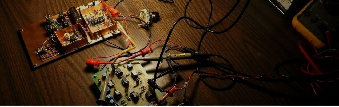
Here’s a few pix’s of the build so far:


Also I put together a small panel that holds the coax connectors for system I/O:

The 145 MHz bandpass filter needs some tweaking from that of the original design of a 144 MHz up a MHz by trimmer cap adjustment and spreading out the resonator coils a bit. I’m thinking about how to terminate the bandpass filter I/O. Not quite ready for this yet but likely will purchase some SMA bulkhead connectors and a couple of short SMA jumpers…Seems reasonable. For the current build I’m going to use (2) 280 KHz 10.7 MHz ceramic resonators for IF filtering since… well, that’s what I have in the bins. These filters I salvaged from some older portable AM/FM radios I usually pick from various thrift stores around town. Their cheap and contain lots of useful parts. Additionally breadboarded a 20dB 50 ohm in/out attenuator for initial board testing. Always protect the input…
Once the board wiring is substantially completed I’ll 1st start by checking the 12V and 5V connections before inserting the ICs (good idea).
Then it’s time to check the frequency span of the 1st mixer (part of the MC3356 chip). Here I’ll take a look at the VCO sweep voltage range and note those reading, place the the Sweep card in zero span and adjust the center frequency control within those boundaries and see what we get for frequency swing.
Oh and I finally get to use the turns counter knob I picked up many years ago for the center frequency pot..Yeah!

But first I’ve a bit of wiring…
Build something Analog!
Randy
