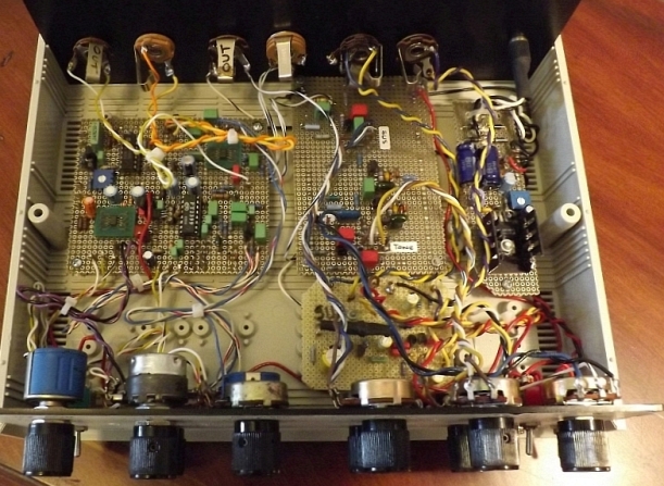
Coming together yes but not without silly mistakes as well. Somehow (not paying attention that is) I managed to wire the individual effects power switches in series so all must be on to bias the boards up…great. So that needs fixed as well as the LEDs need installed and wired up…I guess not to bad.
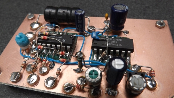
The power source for the effects box consists of a 12Vac wallwort with a standard LM317 regulator configured for 9Vdc output. That can be seen below on the right hand side of the enclosure. Actually that gets me thinking…I’m gathering parts now for an additional effects build called Thor which is a Marshall Super Lead amp simulator which also requires a 9Vdc source. I’ll place a rear panel jack on the current box to bring out the 9V to power the future circuit build(s).
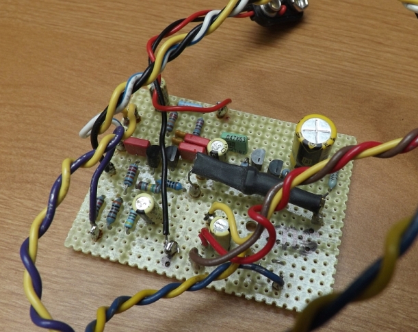
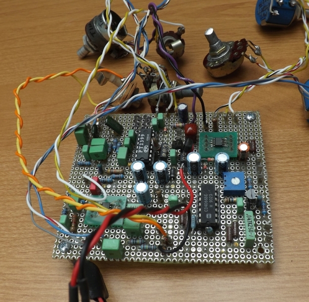
The remaining cards are the sustain circuity (front center), the Big Muff Pi (center rear) and the EchoBase (large card – left rear).
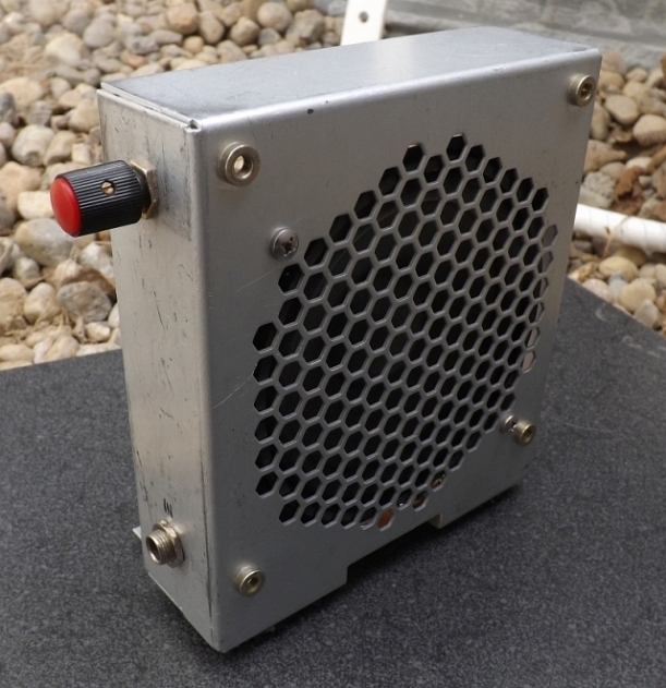
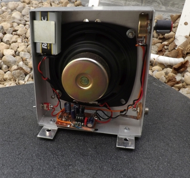
Now that I’ve been blessed to have a guitar back in my life I thought I’d take an inventory of what I’ve got in support of this interest stretching back for so many decades. My first thought was a small, portable low-wattage audio amplifier suitable for a small space. With that I recalled I had put together a 2nd small speaker box to use with an additional SW receiver I put together during the past year but, went unused until now. Nothing really special here… Just a simple LM386 circuit, battery operated with a volume pot and input 1/4″ jack. Here’s a few shots of the completed amp…
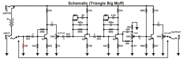
With that completed I need to take a look at where I left off with effects pedal builds back when. I currently have two pedals I finished and tested but never packaged. One is a sustain pedal and the other an Echobase delay, chorus and vibe build, also never properly enclosed. But, at the time, I had built several distortion or overdrive circuits that I was never particularly keen on, and consequently never used. One effect design I’ve been aware of for awhile has been favorite of many artists, including David Gilmour is the Big Muff Pi distortion/sustainer. This was originally designed and sold by Electro Harmonix in the early 70’s and over the years came in many flavors and in fact, varyed from unit to unit due to some part variations. So I decided this would be a good time to give the Big Muff a go.
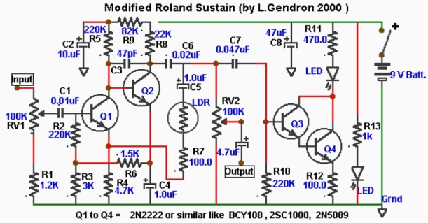
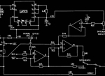
Next is the Sustain effect I put together years back and works very well with good sustain control. Here’s a pic and the schematic…
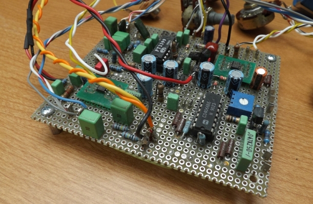
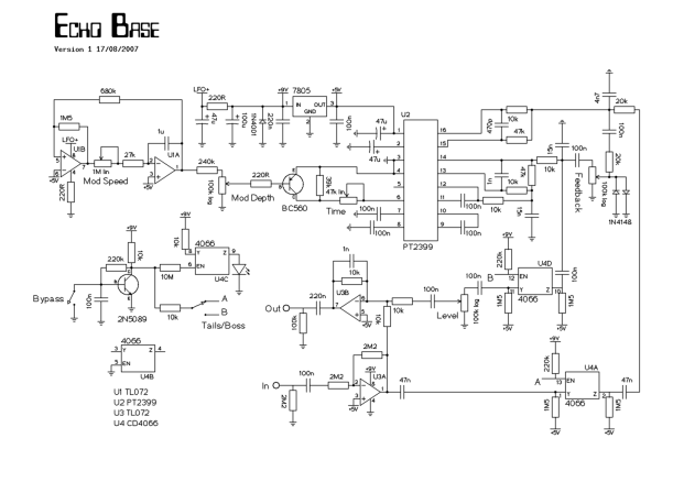
And lastly the Echo base delay circuit that can be utilized as a delay/vibe and chorus with the proper setting. This is the design I probably used the most…
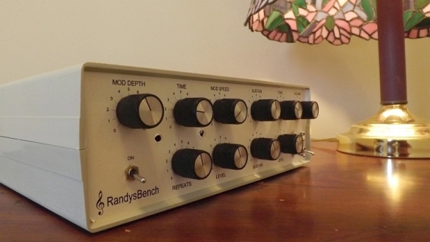
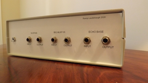
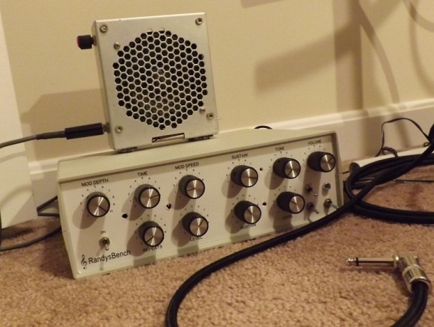
Turns out I’ve got just the box for these various effects on the shelf!
Long ago I sat down with my Sister in front of a B&W television set to watch the Ed Sullivan show, a regular broadcast that all of the family watched each Sunday. This particular Sunday in February 1964 was a special one…The Beatles were on! The hysteria which ensued around the US is something I’ve not witnessed before or since. In fact when “A Hard Day’s Night” debuted at our local theater you would have thought they were there in person based on the amount of screaming going on…well it was pretty exciting for me as well…
So exciting in fact later that year I talked my Parents into a low end accustic guitar and some guitar lessons at our village music store (Spratt’s Music…still in business but a different location and name). Later on I became a gig setup man for a local garage band. After that I ended up moving to Berkeley in the Winter of ’70 looking for some youthful adventures and better weather…Well that’s actually a different story. I did find a nice used Kay electric at a pawn shop down in Oakland which I kept up to the Summer of 1989. A neighbor’s Son took notice of the guitar when we were packing on our way to Arizona and gave it to him. Fast forward 15 years or so later, now living in New York state, I bought a cheapy guitar off of Amazon for $79 bucks (S100 solid body electric) and played that until I passed it on to my Grandson a few years back.
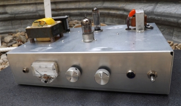
I put together a low power tube amp years back that uses a single 12AX7 and 6AQ5 in a single ended design. It’s puts out about 2 Watts on a good day. I used back to back 12V transformers for filament and B+ voltages…+12V for the heaters and about 150Vdc for bulk. Works pretty good for what it is…
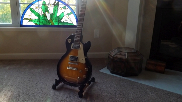
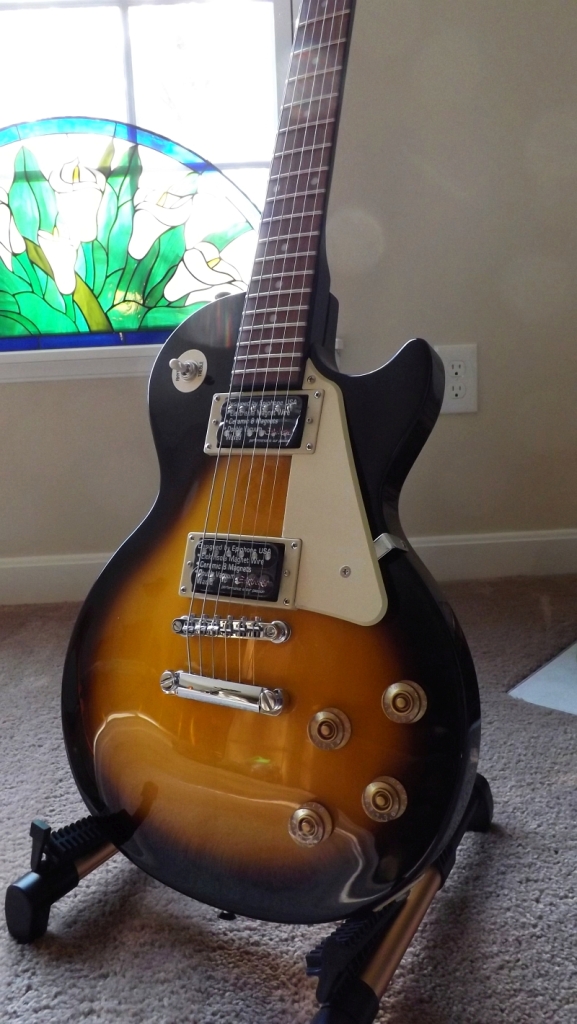
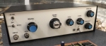
So here I am again with nothing to fiddle with…So back on line again to see what was available in my price range (that my Wife would agree to!) I came across a reasonably priced Epiphone LP style solid body, read the reviews and did some hands on with it at a local music shop and now here it is…
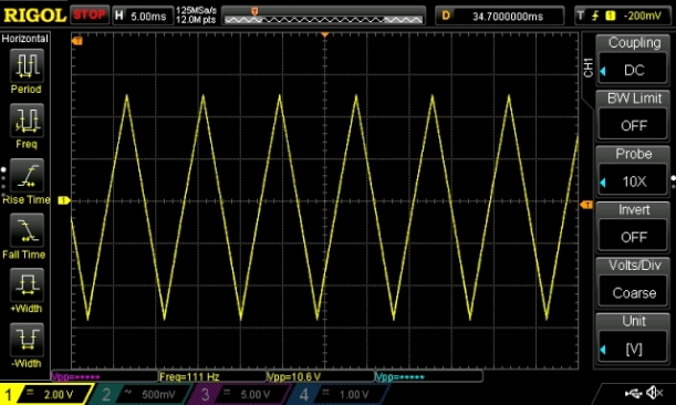
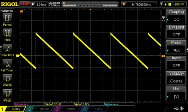
I’ve finished off testing the LFO circuitry and pretty much worked out of the gate. Below is few plots of It’s waveshape’s available…
Triangle
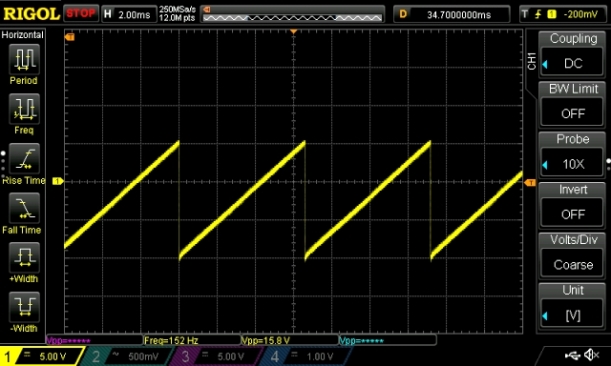
Ramp
Sawtooth
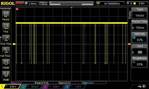
That all looks pretty good for now. Next up is the Noise generator bit. The reversed biased NPN I had put in orginally (MPSA06) was very quite (~50mV). I substituted in a 2N3904 and found the noise I was looking for…
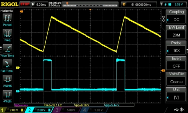
And next the comparator output banging from rail to rail…
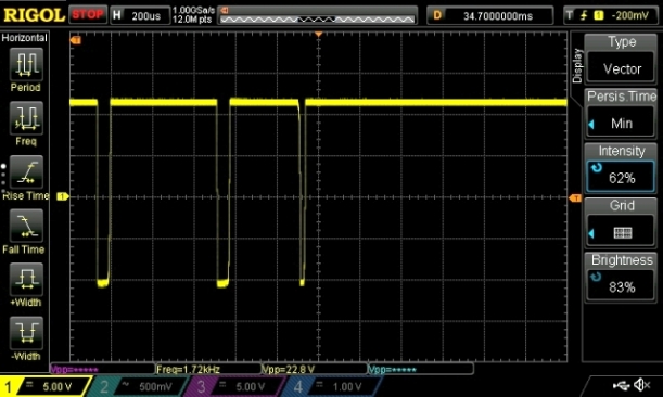
And finally a zoomed in view of above.
Additionally I began looking at the voltage controlled oscillators (VCO1 &VCO2) and so far appear to work well but in a restricted mode of operation (not all I/O connections are implemented). I think what I’ll do is start to work on the real front panel’s art work, get it punched and populated and carry on with testing as it’s being wired up.
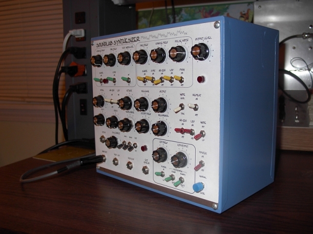
A while back I was bitten by the DIY analog synthesizer bug which in time led me to Ray Wilson’s site and his original Soundlab mini synth design. After collecting the needed parts I set out to perfboard the design, bend some aluminum and wire it all out. But you see, I violated my own electronics project primary tenant. That being to verify proper operation of each module in turn so at the end the project has a much better chance of working as it should. Did I do that? Apparently not…When completed (?) I shouldn’t have been surprised all was not right. It seemed to work, kinda sorta anyway, but not what I expected at least. I got sound, but not the sonic diversity I hoped for. A year later I ended up re-packaging the project into a smaller more compact enclosure, but of course I was still disappointed at the end result. At this point I moved on to other smaller builds, mainly guitar effects, with much greater success. I did learn my lesson and tested, tested and tested from that earlier point up till the present. So I think it’s time to rectify the sins of the past and get the synth properly working to spec. (that’s the plan anyway). Below is a few photo’s of the 1st & 2nd synth incarnations:
…and the 1st build in process:
and lastly the final version from 2005:
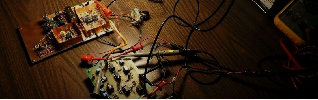
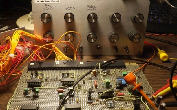
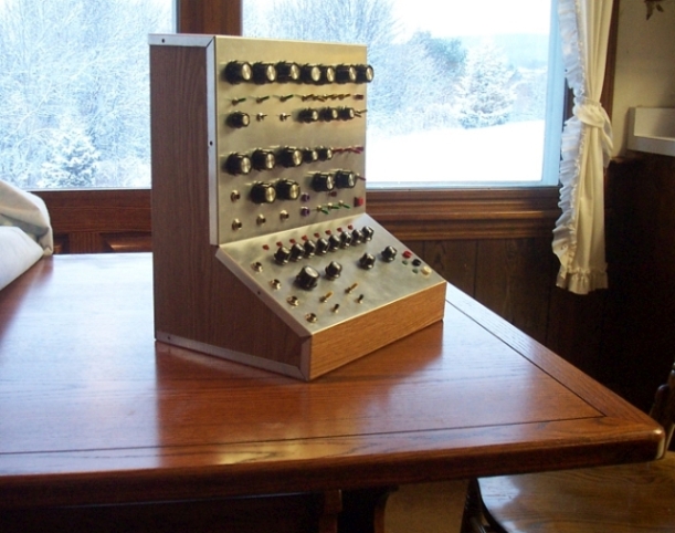
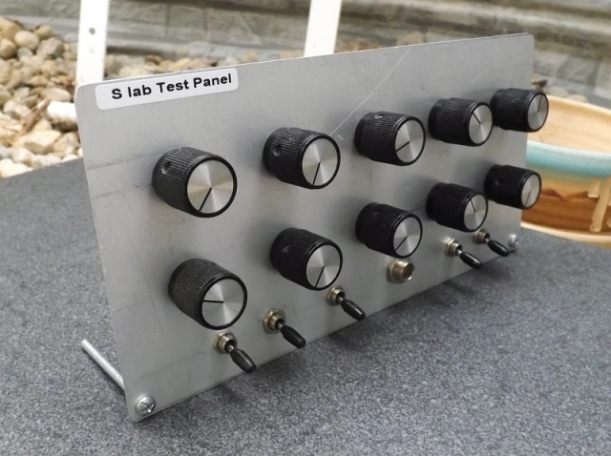
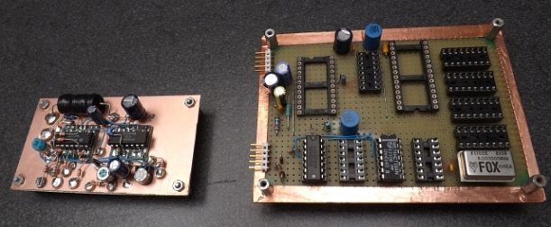
That brings us now to the present. I still have the wired board and the chassis (above) and so I built up a test panel to hold 9 100K pots, 1 1M pot and 5 switches along with a 1/4″ jack for testing purposes…
I actually, to get things moving along, built up a smaller panel with a couple of pots and switches to begin testing the low frequency oscillator (LFO) portion of the design. And of course, is not working correctly…go figure
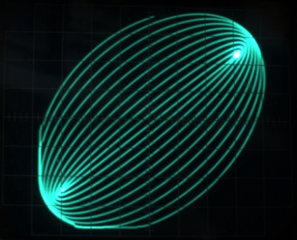
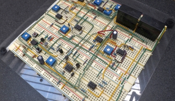
While the Storage-Normalizer is currently on hold I’ve decided to take a look at putting together an older Elektor project which can be found here Built around two damped-sinewave oscillators, it’s pretty easy to breadboard up and get working.
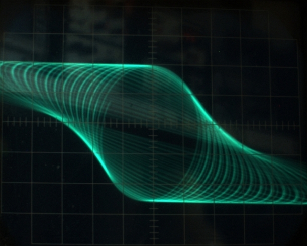
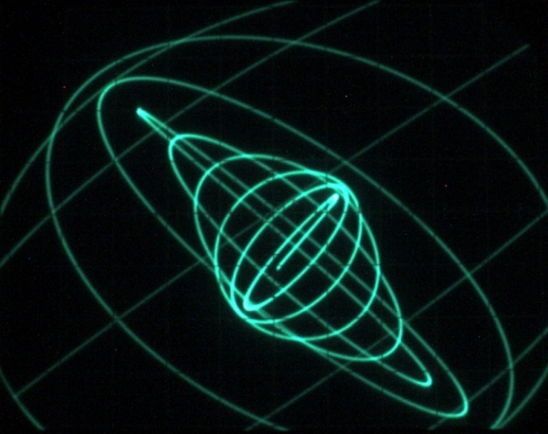
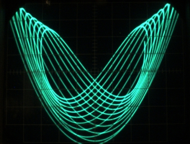
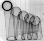
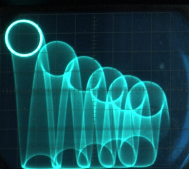
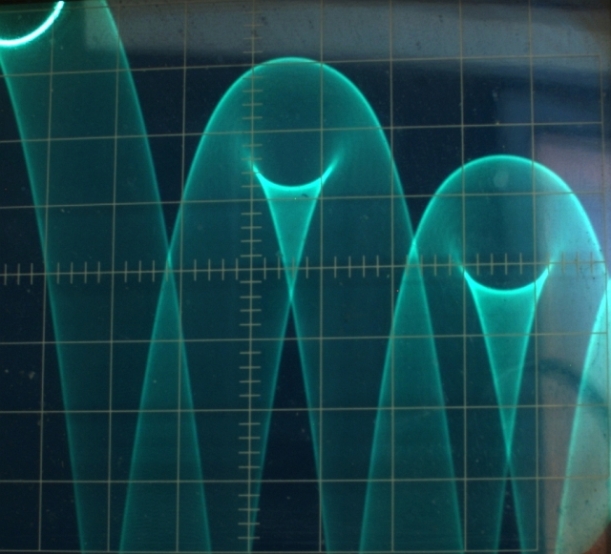
Below is a selection of scope shots to illustrate the diversity of lissajous patterns obtainable… I particularly like the 1st one.
I thought while I’m waiting to get back to the Storage-Normalizer project I’d have a re-look at a project I mentioned back in a post from November of 2017. Beyond an error in the schematic that was corrected, I still had some difficulty with the horizontal drive portion of the breadboarded circuit. At that time I put the project to the side to begin the pursuit of a spectrum analyzer design.
Turns out I had a resistor pop out of the breadboard back then and just found the offender recently. Now it works a treat!
I decided to try out my ZWO astro camera with one of the several low focal length lenses I purchased back when to capture scope screens presented below. Most were between 1.5 and 2.5 sec exposure times.
I might just drag out the old oscilloscope artist project I put together years ago and give it a go with my new found interest!
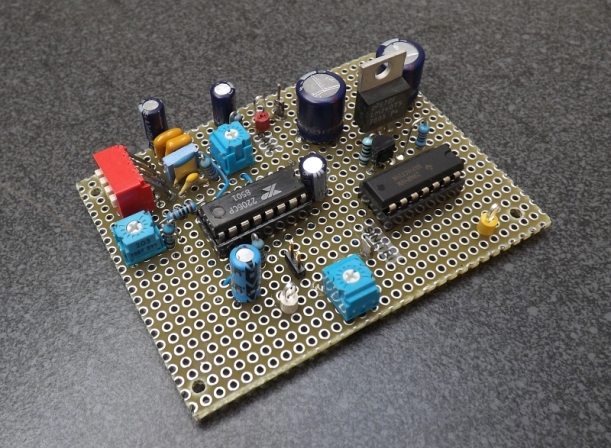
While I wait impatiently for the Storage-Normalizer project parts to arrive I decided to build up a trigger and signal source based on an XR2206 function generator IC of which I happen to have a bunch of. As it is the MC3356 SA does not currently have a TTL level trigger output as yet as this will allow testing be done on the S-N card set. The simple low frequency triangle output can be used as signal souce as well. Below is the finished XR generator assembly:
The schematic is quite similar to that in the XR2206 data sheet for pulse generation… Next is a scope plot of both the triangle source and proposed trigger output. It uses an 74HCT14 hex inverter IC with it’s own 5V supply. The triangle (Ramp) output needs it’s amplitude and offset adjusted to fall within the A/D converter input window. The approx. 32mS duration is just about right for the S-N’s memory capture capabilities.
Another item I might experiment with is a SMT version of a compatible A/D converter, the HI5714 A/D. I sampled some of these back 8-10 years ago for a project that ended up a bit much for me too chew so I went in a different direction. This might fill in temporarily till the parts arrive. But still, I don’t have a sub for the video D/A part…
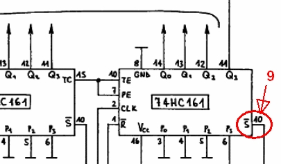
In the process of wiring up the AD/memory card I discovered a minor error in the schematic involving duplicate pin numbers on each of the four 74HC161 counters used. Two pins, being marked as pin10, it turned out that the S/bar input should be pin 9 as shown below:
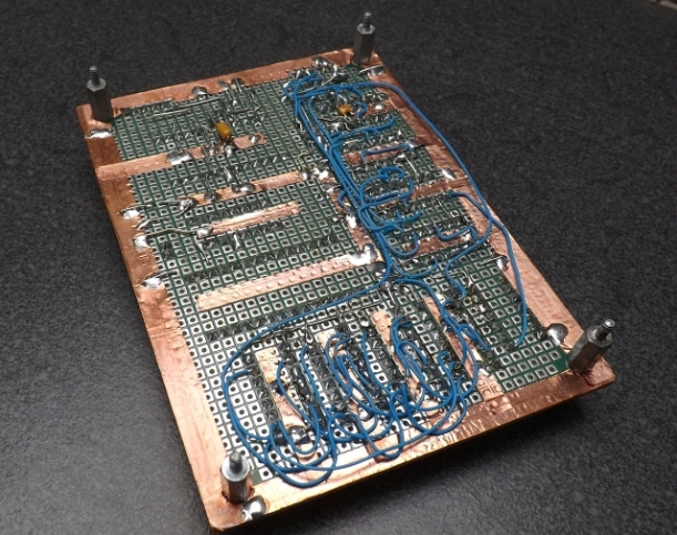
I discovered an old Tektronix scope calibrator PCB I had received back in the late 80’s and thought it would be a nice addition to the SN project. This would allow a low frequency internal signal for calibration purposes. I’ll use a rotary switch to couple in int/ext signals to the A/D converter section. I completed the interface board as shown below. But for now the wiring continues…